IN DEPTH — Developing Digital Visual Literacy of Complex Digital Objects: Deconstructing CAD
- Apr 8
- 11 min read
This is the third of a three-part series by Aliza Leventhal and Julia Larson on enhancing archivists’ visual and technical literacy in handling complex digital objects.
Visual Components of CAD Interfaces: What You See Isn’t Always What You Get
For all of its functionality enhancements over its history, the interface of most Computer-Aided Design software has remained relatively unchanged: the black or gray field of the drawing space is framed on three sides by the top navigation ribbon hosting a variety of menu browsers, the tool palettes along the right or left side and the command prompt at the bottom of the program’s window. While most programs offer robust customization for how tools, features, and data are displayed, the digital visual literacy of CAD software users is reinforced by a consistent layout, icon selection, and view settings. All frequent computer users have some capacity to both create and to understand visual materials created with a computer (e.g., recognizing a sign-in box, using the floppy disk “save” icon despite the dramatic decline of this format decades ago); these are skills developed due to frequency of use, consistency of activity, and intention to learn. For the past several decades, designers in the United States have started their relationship with CAD and related software during their academic training, making ‘computationally-generated imagery [sic] a new vernacular language of architectural representation’ (Cardoso Llach, Kaltman et al, 2021).
The learning curve is deceptively steep for archivists who have not had the benefit of a scaffolded and extended training with design software. Without that foundation, attempting seemingly simple tasks of opening any of these programs to render a file from a collection— even with a writeblocker, with an access copy of the file, and other archival failsafes in place—can be intimidating. This is partially due to the incongruous comparisons made against the analog counterparts of these complex digital files. Comparisons ranging from fragility of media (crunched trace paper can be relaxed and flattened vs. missing xrefs due to poor file management prior to a collection transfer), readability (a reverse sepia print that requires a mirror to read the text vs. a locked PDF set of drawings without any password information in the records), as well as authenticity (an ink-signed and stamped set of drawings vs. multiple copies of a file with “final” in the filename). Setting the technical infrastructure and other financial concerns aside for a moment, the transition to digital design practice has produced an exponentially more complex landscape for archivists to manage in order to establish the same level of certainty in their ability to appraise, interpret, process, describe and provide access to collections as they have enjoyed thus far working with analog records (as unwieldy as they are in their own right).
That complexity is compounded by the mixture of jargon and visual cues of each software. While most design software has a similar window layout (as described above), each vendor has created its own vocabulary. What has been shared in this blog series is just a fraction of the variation and serves as an introduction to some of the considerations archivists need to account for when receiving collections of born-digital design materials. This last part of our series intends to build the reader’s understanding of the general features of a CAD software’s interface through the categories of navigation, drawing spaces, and visual properties.
Navigation: Menus, Command Line, Views
Most CAD software offers a mixture of customizable toolbars, context-sensitive menus, graphical feedback, and command line prompts to develop drawings. The evolution of features illustrates an emphasis on direct manipulation and visual interaction, while retaining the option for textual commands. These types of interactions include adjusting the zoom or focus of the screen, panning and scrolling around the unlimited drawing space, or altering the view type, such as 2D or the various 3D options.
The variety of these tools enables users to work more efficiently than hand drawing, such as drawing with a high level of detail at scale, or making an update to multiple related parts of a drawing simultaneously. These tools are highly customizable, which allows users to tailor the layout of their interface to their specific needs and preferences. Being aware of the variety of working practices of designers with these highly customizable tools can enlighten the archivist working with collections of born-digital design records. Knowing what features were more important or prevalently used is akin to awareness of earlier designers’ proclivity for colored pencils, a certain pen type, or the practice of making multiple copies of particular drawings.
These tools can be organized into four categories:
Command line: the command line has been a mainstay of many CAD software as a text-based interface to implement a variety of granular and scalable actions upon a drawing or to reveal specific Layers or Attributes.
Icon-based toolbars: graphical bars typically located along the edge of the drawing space that provide ready access to frequently used commands.
Context-sensitive menus: menus prompted to appear when specific tasks are undertaken, or Objects or Blocks are selected.
Graphical feedback mechanisms: component-specific features such as highlighting or snapping of Objects or Blocks, as well as dynamic previews that facilitate precise assembly of the drawing.
Archivists can also leverage these features to explore and understand the composition of a CAD drawing, such as using the command line prompt “explode” to see the various Objects and Blocks a drawing is made up of. There are countless tutorial videos available on vendor websites and on social media sites like YouTube and Are.na that designers use to learn efficient workflows that maximize the capabilities of these robust software programs.
Model Space and Paper Space (AutoCAD)
Model Space is the drawing interface screen for AutoCAD where designers can create drawings with objects, blocks, libraries, layers, and xrefs. Model Space is analogous to the drawing board in the physical realm, but with an infinite amount of space. The constituent parts of a drawing can be created and combined in Model Space without constraints of drawing size. The designer sets the parameters of the drawing at a 1:1 scale (click this link or this link for more information), irrespective of the final printed sheet size. The black background reinforces this sense of infinity, while also allowing for contrasting colors and lineweights to clearly delineate specific components of a drawing.
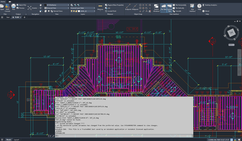
Model Space is highly customizable, with personalized settings and templates for toolbars, view windows, program settings, and more; however, these settings do not transfer with the files, so emulating the exact environment at the time of file creation is not always possible. In the following image from Model Space, the detail drawings and associated annotations are spread out over the screen, in various states of completion.

Paper Space can create many printed versions from one drawing, for example, both sections and elevations, pulling electrical or mechanical from floor plans, etc. Instead of the black background that suggests infinite space, Paper Space works with a white background to reinforce the expression of the physical output. Paper Space is bounded by dimensions, scales, and proper sizing of the drawing, and mediates the intersection between the infinite Model Space and the constraints of paper; therefore, Paper Space is not as customizable as Model Space. The Layout bar along the bottom of the screen toggles between Model Space and Paper Space, and viewports can be utilized to envision the printable space. The following image is the Paper Space version of the previous Model Space image. Each detail is annotated, and the components all conform to the size and scale for the final output.

Model Space/Paper Space can offer a window into the creative process of a designer, as it exposes how a designer structures their drawings and indicates what their intended output was. Archivists could discuss with the donor or firm their CAD process to understand: if a drawing is an iterative or final view, what do they create in Model Space, how do they parse views of a Model into Paper Space to be printed, and where is the final view (is it locked against changes or saved as a different drawing). By understanding the designer’s creative process, for example, if they sketch the schematic design by hand and then transfer it to the computer, an archivist can begin to recognize project design stages as displayed in CAD.
Models (MicroStation)
As we have shown throughout this series, each software program utilizes a vendor-specific controlled vocabulary to define the component parts of the interface. MicroStation uses three different Model areas for working with various aspects of drawings.
Design Model: the default view where the drawing typically begins. Similar to Model Space in AutoCAD, it has a black background where elements, cells, and libraries of components are placed to create a drawing.
Drawing Model: contains all of the descriptive and administrative metadata about the drawing, such as the annotations, scale info, etc. It is analogous to printed or handwritten schedule sheets and manufacturer information in analog drawings. It has a gray background to differentiate from the other two Model areas.
Sheet Model: is a mock-up of the printed drawing, analogous to the final working drawings in analog drafting, and to Paper Space in AutoCAD. It has a white background for ease of printing and viewing the components for quality control.
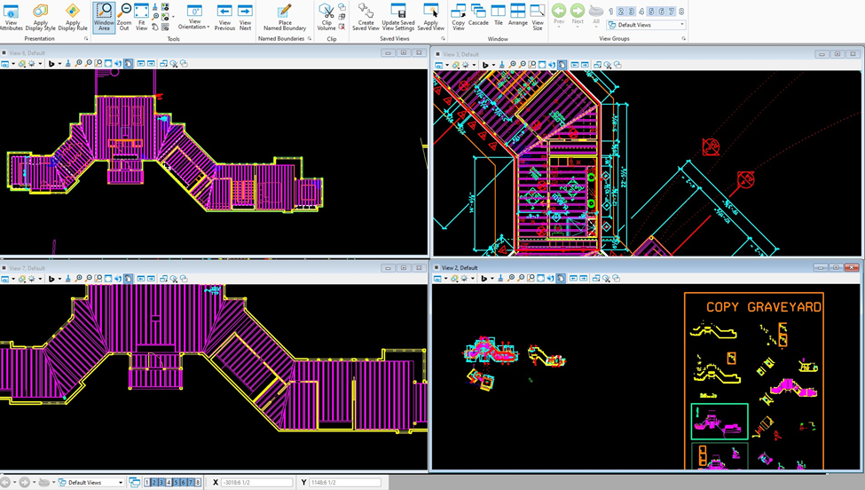
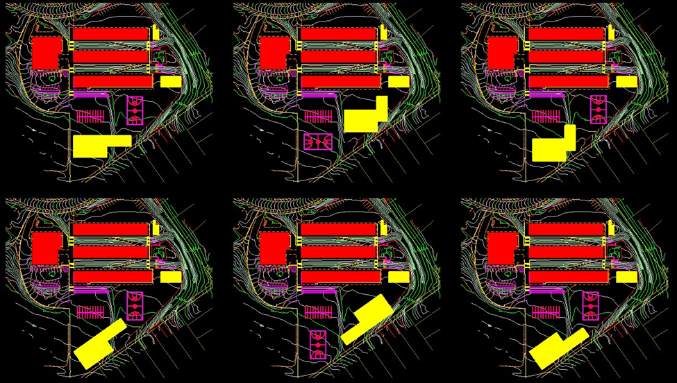
MicroStation gives you the option to customize your screen to show multiple View Groups, which are user-defined, pre-set views of Models. For example, in the above, one view shows the plan with furniture, another view without, a third view is an annotated plan, while a fourth view shows additional elements used in the Model. The settings and customization can add additional context to the design process, and can contain multiple Models within the View Group for comparison and collaboration.
Plotting/Printing/Publishing
For many years in the design fields, "printing" was defined as printing text materials, such as specifications, on a small-format printer. "Plotting" was the physical output of vector graphics, such as CAD drawings printed on a large-format printer, either in-house or outsourced to a third-party reprographic company. In the early days of CAD, large-scale pen plotters were used to print the final drawings. These pen plotters utilized different types of pens (ballpoint, felt, various ink styles), so a clean and properly scaled version of the drawing was needed for plotting. Pen plotters fell out of favor as technology changed, and high-maintenance pens (few color choices, limited lineweights, pens clogging and needing to be refilled, etc.) were replaced by less labor-intensive options. See links here and here for historic plotter images.
Publishing is the digital distribution of electronic drawing sets in AutoCAD, generally as DWF, DWFx, or PDF file formats. For example, publishing trade-specific views of electrical or mechanical systems to send to contractors. Sharing of files electronically is defined as publishing an i-model in MicroStation. The i-model is a semantically rich data file that is read-only and capable of containing all project data in a container that is interoperable between programs. This allows for the sharing of information across platforms, irrespective of proprietary formats.
Both AutoCAD and MicroStation allow for printing many different outputs from one file, so an understanding of the standards and processes of a firm will help an archivist to determine if/when/how a specific file was printed/plotted/published. Archivists will need to contend with printed (and printable) CAD files in various ways– as entities in Paper Space, as published files transferred between designers and collaborators or clients, printed at various stages in the design process (schematic, development, 50, 75, or 100% construction drawings), and possibly printed drawings that do not match any CAD files for the same ‘final’ project. Hybrid archival collections can and do contain all of the above, and archivists need to determine the digital components' relationship to the physical materials, if there is one.
Visual Properties
The visual properties described here are often customized with firm-specific standardization templates to ensure consistency and professional output across team members. Archivists should inquire with donors about these template files and look out for their specific file type extensions such as .dwt, .ctb, .stb., or .lin.

Lineweights: the thickness of a line, measured in millimeters. In combination with color, this aspect denotes the meaning of each line in the drawing as defined by specific standards. In the early CAD days, lineweights were listed out by hand and could be contained in the analog documentation to define the content of the drawing and to determine which pen should be used to plot the printout. They are often customized within a firm using a standardized CAD template (.dwt) and accompanying plot style tables (.ctb or .stb). The industry standard is to use by-layer properties rather than assigning lineweights directly to objects, allowing for easier, centralized control of drawing standards.
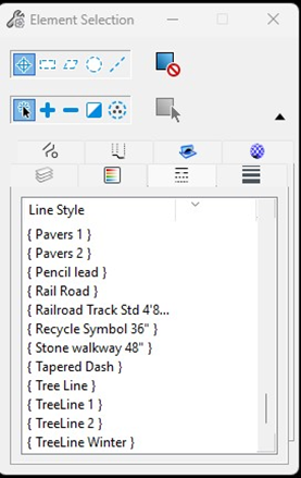
Linetypes/Linestyles: the structure of the line, whether it be dashed, dotted, solid, or a combination thereof, provides additional information about the line’s role in the drawing. Firm-specific linetypes and linestyles involve defining custom patterns that can range from simple dashed lines to complex lines containing text or shapes, and storing them in a standardized .lin file.
Fonts: a selection of font choices used for the title block and other textual Attributes in a drawing. The use of custom or proprietary fonts is a frequent practice that will give an error code in modern software programs, especially for legacy files for which font packages were often omitted or lost during systems and software updates over time. Text or Symbol Fonts can be stored as SHX files (aka shape files); if they were not transferred with the drawing (or moved, renamed, or deleted), a pop-up message will appear with instructions to ignore or specify a replacement file.
Colors: can be used to differentiate Objects and Blocks, and/or on specific layers to delineate electrical or mechanical plans, for example. Color can be used in combination with line weight and line style to define entities or layers. Firm-specific colors and standards typically map specific index colors to pen line weights for consistent printing, often utilizing a variation of the ISODIN standard (e.g., Red=0.18mm, Yellow=0.25mm, Green=0.35mm, Cyan=0.50mm, Blue=0.70mm, Magenta=1.00mm). Companies often use custom .ctb or .stb plot styles to assign unique screening (transparency) to colors to enhance drawing clarity.
Conclusion
Developing an internal sense of digital visual literacy for design records is a lengthy process that is best approached incrementally and involves developing a foundational understanding of the fields and components in standard CAD interfaces. Recognizing common terms and images displayed in a software program can lead to greater familiarity with the files and an increased level of comfort with components and proprietary formats. Utilizing the online program manuals for each CAD vendor can be helpful, as well as literature by, for, and about each proprietary software program.
The goal of this series (links to Part 1 and Part 2) has been to provide a window into common components and vocabularies used by proprietary software programs to help archivists understand the building blocks of CAD files. We have only lightly touched upon some of the structural facets that can cause issues with readability and rendering, such as layers and xrefs, as well as external databases for attributes and libraries. These components require a baseline of digital visual literacy surrounding the software interface and its ability to render a file as intended by the designer. Our exploration of CAD focused on AutoCAD and MicroStation, to highlight the complex vocabularies and visual cues unique to each program and to show how the same concepts can be viewed in different interfaces. The ability to extract and print many different views of one file creates additional issues for archivists, since many times, what you see is not always what you get.
References and Additional Resources
[1] 13 Essential AutoCAD User Interface Guide for 2025: https://gifluent.com/autocad-user-interface/#:~:text=Dynamic%20Input:%20Displays%20command%20prompts,selected%20objects%20in%20a%20palette
[2] Tennessee Department of Transportation MicroStation V8i Course Manual: https://www.tdot.tn.gov/PublicDocuments/%5CDesignDivision%5Cassistant_engineer_design%5Cdesign%5Cv8%5CMicroStation%20V8%20Manual.pdf
[3] How I Stopped Worrying and Learned to Love AutoCAD: https://papers.cumincad.org/data/works/att/acadia05_094.content.pdf
[4] Deconstructing the Software Interface: A Critical Close Reading of AutoCAD: https://papers.cumincad.org/data/works/att/ijac20042301.content.pdf
[5] Landscape Research Record: Perspectives on Documentation Standards in Design Education: A Strategic Approach to AutoCAD Implementation: https://thecela.org/perspectives-on-documentation-standards-in-design-education-a-strategic-approach-to-autocad-implementation/
[6] Bentley MicroStation User Manual: https://docs.bentley.com/LiveContent/web/MicroStation-v2024.2/Help/en/html5/topics/123015/GUID-F8CE58A4-82BD-4212-99EC-D5E6F331B6D2.html
[7] Autodesk AutoCAD help center: https://help.autodesk.com/view/ACD/2024/ENU/?guid=GUID-990538B6-DDA1-4190-BCC0-BB5BA94C9879
[8] Design Software History: The Evolution of User Interface Design in CAD Software: From Early Innovations to Modern Usability Enhancements: https://novedge.com/blogs/design-news/design-software-history-the-evolution-of-user-interface-design-in-cad-software-from-early-innovations-to-modern-usability-enhancements?srsltid=AfmBOoqPg4aqhcaPWmRoAIAyl907z1k7LtvWDxN590kQFrHDuSCYAGIK
[9] Cardoso Llach, Daniel, Eric Kaltman, Emek Erdolu, and Zachary Furste. “An Archive of Interfaces: Exploring the Potential Of Emulation for Software Research, Pedagogy, and Design.” Proceedings of the ACM Conference on Computer-Supported Collaborative Work, Virtual, 2021. https://dl.acm.org/doi/abs/10.1145/3476035
Aliza Leventhal, Library Director, Fleet Library - Rhode Island School of Design
Julia D Larson, Collections and Digital Archivist, Environmental Design Archives - University of California, Berkeley


Comments